With availability of nVidia RTX graphics cards, ray-tracing in real-time applications, most especially Unity HDRP and Unreal Engine, has become a viable solution. Benefits are improved image quality and reduced production times, although these can come at the expense of performance unless carefully managed.
During lockdown and persisting into 2021 I’ve experienced a large (read: huge) increase in demand for video production using real-time engines, mostly Unity but also Twinmotion, and this looks as though it’s going to persist. For the sake of my sanity, this is an overview of a production pipeline using Unity HDRP to produce commercial videos for B2B applications.
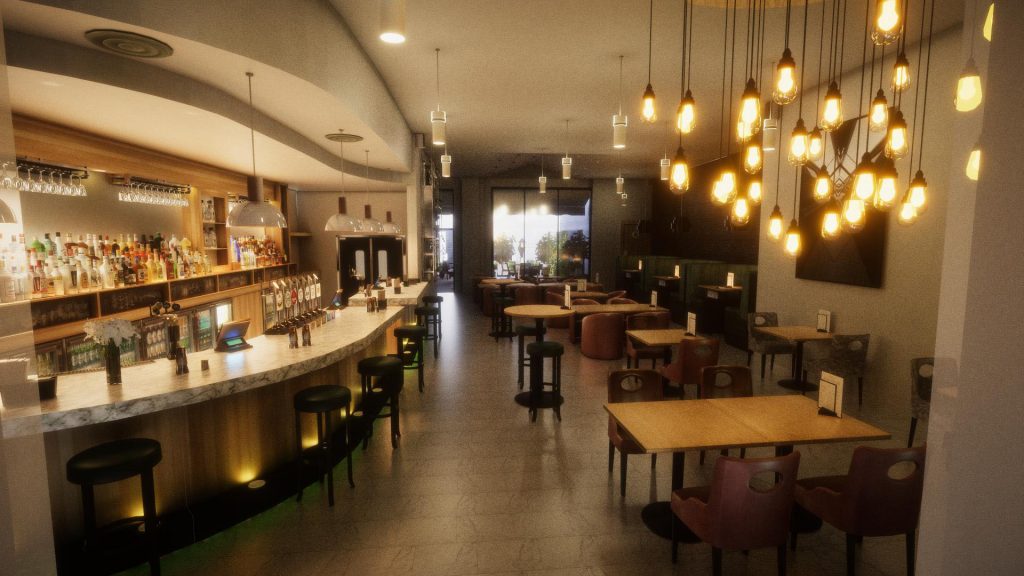
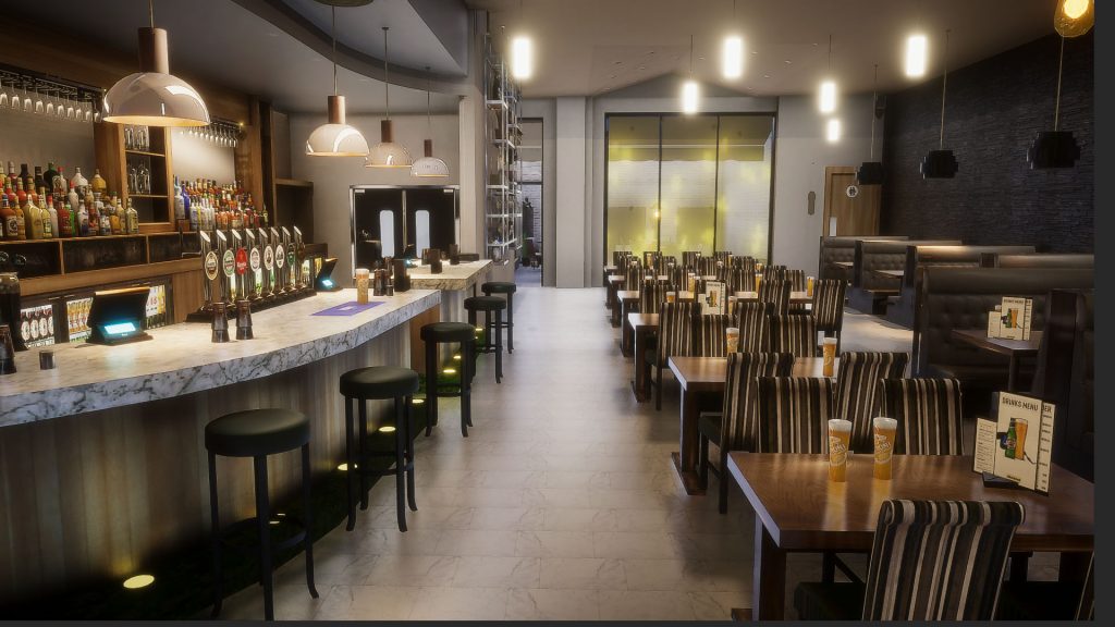
Interior using Unity HDRP with path tracing. 5000 samples, c.7 mins per frame at 1920×1080.
Context
I work for Kantar in the consulting division, my client is Unilever and I live in the dark recesses of the Customer Insight and Innovation Centre in Leatherhead, at least I did when there wasn’t a global pandemic on. The role originally involved creating real-time projects for research, including quantitative and biometric research, as well as commercial presentations. Using real-time to produce videos for wider distribution has become very popular though, and methodologies have had to adapt accordingly.
Kantar have developed a real-time tool called VR INFINITY, which is a combination a Unity front-end and a cloud-based CMS for content that is designed to run on relatively low specification laptops. The benefit of this is category managers and marketing executives are able to produce and experiment with their own 3d scenes, making it an effective tool. In some situations though, there is a requirement for higher quality visualisations, hence HDRP.
The aesthetic objective here is to match or beat the visual quality provided by teams at advertising agencies using offline renderers such as VRay and Corona. With caveats, this is broadly achievable.
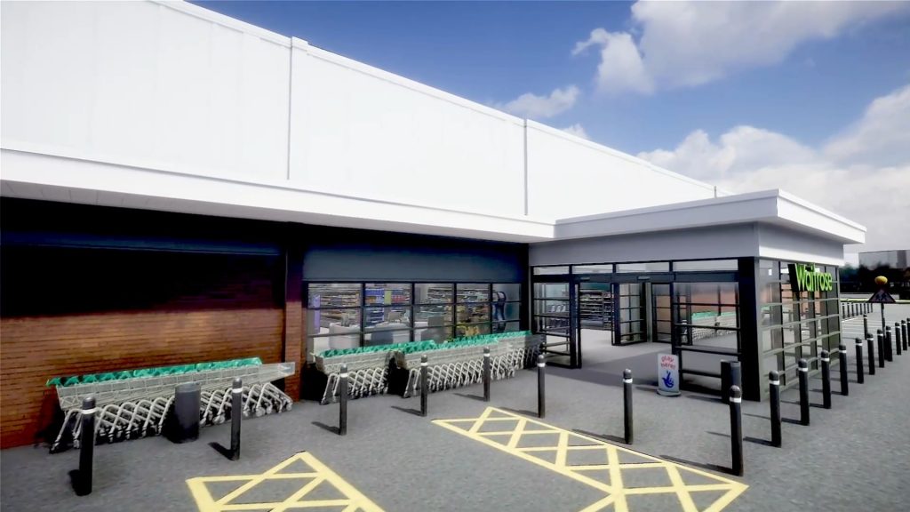
Exterior with HDRI map, direct light, using screen space reflection, screen space global illumination and screen space ambient occlusion.
Back to basics
‘In 3d computer graphics, ray tracing is a technique for modelling light transport for use in a wide variety of rendering algorithms for generating digital images.’ There are a number of variants on the theme of ray-tracing, and as noted by Wikipedia they come with increasing computational cost. As a process though ray-tracing is inherently parallelisable, which makes it viable for RISC / ARM architectures such as graphics cards. (RISC: Reduced Instruction Set Computing – often GPU – vs. CISC, Complex Instruction Set Computing. With apologies for generalisations, but think of this as the difference between multiplying 7×5 and adding 7+7+7+7+7. The addition will process faster on a RISC processor than the multiplication will on a CISC processor, such as an Intel CPU. Amongst other things, this is why Apple have recently ventured into ARM based architectures for computers, in addition to phones and tablets).
In nature, light is emitted by a light source and is either absorbed, reflected, refracted or fluoresces with the surfaces it meets. In doing so some characteristics of the light may change, for example its colour may appear different as a result of interactions. Think of a brightly coloured ball being placed by a neutral coloured wall, and note the colour of the reflection on the wall’s surface. Such interactions cause the visual richness and complexity of the world we see around us.
Inevitably, simulating these complex interactions is a compute-heavy task and requires multiple solutions. In addition to real-time ray-tracing in the form of ambient occlusion, reflections and global illumination, physically based rendering techniques (PBR) using realistic materials enabled by microfacet BRDFs such as GGX to enable greater realism, and are now supported by powerful hardware. It’s a fun time to be involved with computer graphics (but then, this has always been true).
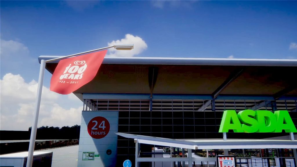
Exterior with HDRI map, direct light, using screen space reflection, screen space global illumination and screen space ambient occlusion.
A brief look at Physically Based Rendering
Without getting into too much detail, PBR shaders use micro facet BRDFs such as GGX. Bi-directional Reflectance Distribution Functions have been at the heart of computer graphics pretty much since day one, and have frequently gone by the names of their creators, such as Blinn, Lambert and Phong. In recent years normal maps have replaced bump maps as the default method for describing surfaces details that are too small or numerous to be effectively modelled by geometry, and have been an enabler for PBR.
‘Microfacet BRDF models are based on a geometrical description of the material surface as a collection of microfacets whose dimensions are much greater than the wavelength.’ (EPFL, Lionel Simonot, Université de Poitiers, France).
Arguably the key term in BRDF is ‘bi-directional,’ as it refers to the effective reversibility of a ray path, meaning the effect of a ray emanating from a light source can also be measured by a ray emanating from the camera / eye, which in many ways is a medieval concept. (Some monks thought ‘light’ was a property that emanated from the eye. Just shows how wrong you can be). Underlying this is conservation of energy, meaning that to be physically realistic no more energy can be output than is input.
PBR shaders will have a number of different components depending on the specific workflow they’re designed for (such as metallic or specular). These may include albedo, metallicity, roughness/smoothness and surface normal, as well as height maps, ambient occlusion, detail maps etc. Like HDRI maps it’s possible using photographic equipment to produce these from scratch, but doing so is generally not a trivial exercise. Fortunately tools such as Substance, Quixel Mixer and Materialize allow for the creation of PBR shaders in a more streamlined fashion. Modelling both metallic and dielectric surfaces has become more accurate and more straightforward.
The point here is simply that PBR shaders have increased the level of visual fidelity in computer graphics in representation of materials, ray-tracing has increased the level of fidelity with respect to lighting, and GPU acceleration has enabled these two to be combined in a timely fashion – mostly. We’ll come onto path tracing in a bit.
Finally… The nuts and bolts.
So after a lengthy preamble we’ll get on to using this stuff in Unity HDRP. The objective is to go from a medium fidelity render of a real-time scene to a substantially higher fidelity render / animation with minimal intervention. Let’s look at the source material:
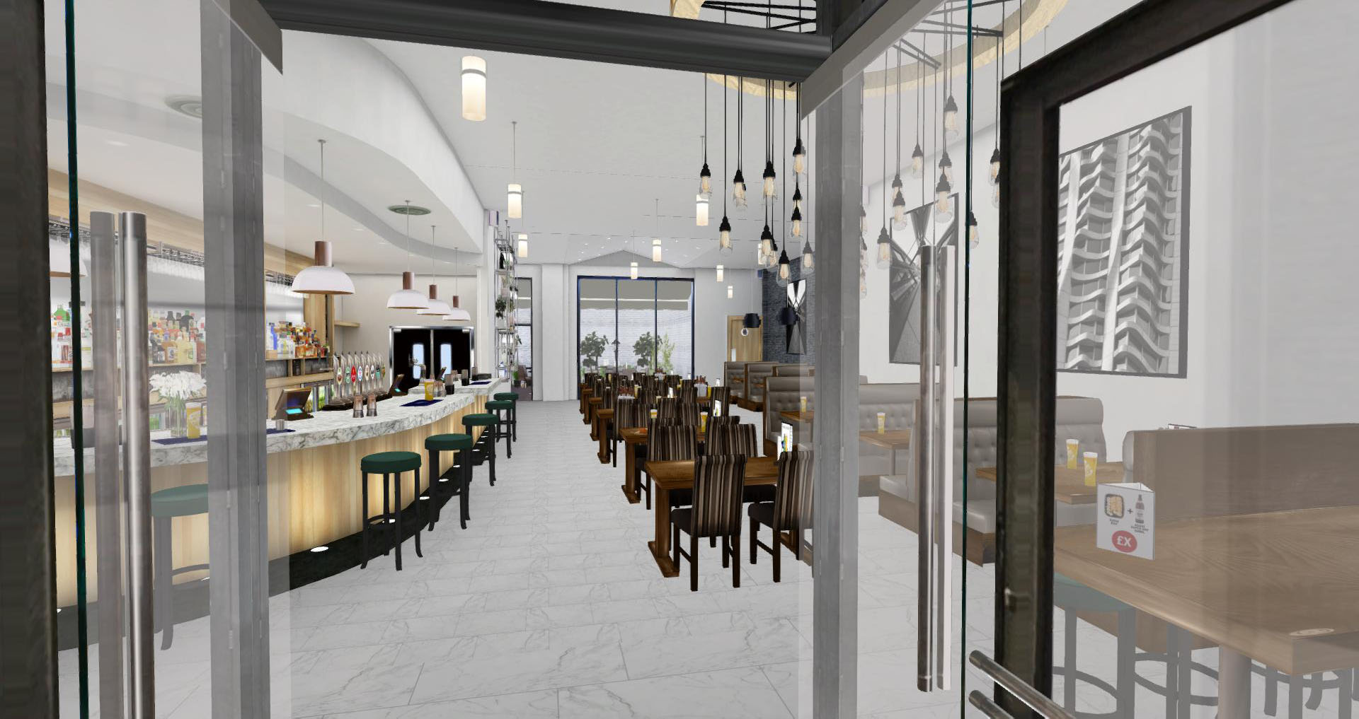
The scene shown is part of a large series of models developed by Kantar for use on comparatively low performance devices. All models and textures have been built from photographic site surveys, and in this application are all unlit. They’re used in conjunction with planograms and data visualisation, often in the context of very large retail environments (think: the biggest stores Walmart has).
Using real-time ray-tracing in HDRP we can, with comparatively minimal intervention, improve rendering quality substantially (but of course only on computers with ray-trace compatible graphics cards).
Working with lights in real-time ray-tracing is a delight in comparison to off-line renderers. Positioning spots and are lights and seeing the effect of global illumination changes as they occur is an enormous workflow benefit. It also allows for experimentation, which is always a benefit.
Finally, an example of a path-traced version of the same scene:
Ray-tracing is used here to avoid or at least reduce the need to bake light maps into models, and to improve on the quality of screen space reflection, GI and AO, the disadvantages of which revolve primarily around their inability to assess effects outside of the camera frustum, resulting in artefacts with moving cameras.
Kantar’s library of scenes and retail environments is a huge and incredibly flexible resource for any company involved in retail. For more information contact Carl [dot] Goodman [at] Kantar [dot] com.
Recent Comments